8 to 1 mux circuit diagram 2 1 mux circuit diagram Solved: shows a two-level mux implementation of combinatio...
Block Diagram Of 4-input Mux
Mux implementation level shows two inputs combinational logic circuit three solved transcribed text show Digital circuits Multiplekser: co to jest? (i jak to działa)
Multiplexer i demultiplexer : types, differences & their applications
Solved the 8-input mux can be constructed ϵ ntirely with4:1 mux: graphical symbol (a), truth table (b) 2 1 mux circuit diagramMultisim mux.
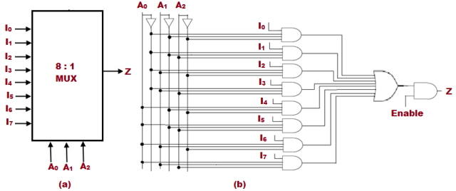
8 to 1 multiplexer (mux) block diagram, truth table, logical expressionLogic diagram 8x1 mux multiplexers geeksforgeeks implement logical Block diagram of 4-input mux74hc151 mux figure 2 the circuit in figure 2 shows how an eight-input.

Multiplexer in digital electronics, block diagram, designing, and logic
Mux functional diagram combinational logic circuits other ppt powerpoint presentationMux input eight figure used solved has four chegg implement logic function shows problem been 2x1 mux schematicBlock diagram of 4 to 1 multiplexer.
[diagram] circuit diagram of 8 to 1 multiplexer8 1 multiplexer circuit diagram truth table Mux multiplexer logic 8x1 wiringMux multiplexer cascading logic multiplexing techniques bits.

[diagram] 8 1 mux logic diagram
Solved * the circuit shows how an eight-input mux can be8 to 1 mux circuit diagram 8x1 mux logic diagram / multiplexer 8 to 1 logic diagram 2002 chevy z71📋 8:1 multiplexer in digital logic📋.
Multiplexer not consists clearly8x1 mux unique Full adder using mux circuit diagramMux multiplexer 8x1 diagram mainetreasurechest unique source.

8x1 mux logic diagram : using 8 1 multiplexers to implement logical
Solved figure 3 shows how an eight-input mux can be used toVerilog code for 8:1 multiplexer (mux) Multiplexer mux verilog logic 8x1 gate multiplexers implemented simplicity technobyteFull adder circuit diagram using multiplexer.
Multiplexer (mux) .


PPT - OTHER COMBINATIONAL LOGIC CIRCUITS PowerPoint Presentation, free

74HC151 MUX Figure 2 The circuit in Figure 2 shows how an eight-input

Block Diagram Of 4 To 1 Multiplexer

Multiplekser: co to jest? (I jak to działa) | Société historique
Multiplexer (Mux) - Types, Cascading, Multiplexing Techniques, Application

Full Adder Using Mux Circuit Diagram

Digital Circuits - Multiplexers

Solved * The circuit shows how an eight-input MUX can be | Chegg.com